INSIGHTS
10 min read


Published on 04/18/2024
Last updated on 04/18/2024
LLM inference optimization: An efficient GPU traffic routing mechanism within AI/ML cluster with rail-only connections (Part 2)
Share
Part 1 of this blog series on training LLMs introduced a traffic health-score-based model implemented on a state-of-the-art GPU cluster. This cluster comprises multiple high-bandwidth interconnect GPU domains connected with one level of rail switches. Each GPU has two different types of interfaces: the r-interface, which is an RDMA-capable NIC interface connected to a rail switch, and the d-interface, which is the interface in a high-bandwidth interconnect domain. The rail switch has a unique characteristic: each rail switch connects all GPUs with the same order number (or ranking) within each domain.
We then defined a normalized h-score for each rail switch and each interconnect domain. Each GPU’s r-interface or d-interface and associated link will be assigned to the h-score of the connected rail switch and domain. We further extended the h-score concept to any network path. Consequently, each GPU will have an h-ratio, γ, representing the ratio of the h-score of the GPU’s r-interface to that of its d-interface.
Additionally, we defined two basic types of paths, rd-path, and dr-path, demonstrating how we can determine the optimal path from a source GPU G1 to a destination GPU G2 by comparing their respective health ratios. This can be stated as follows: we should choose G1’s r-interface when γ(G1) > γ(G2), and choose G1’s d-interface otherwise.
Diving further into case 3 of Part 1, we'll explore more complex paths beyond the rd-path and dr-path types. Firstly, a new type of path is introduced: drd-path. Then, we analyze and identify the exact conditions under which drd-path should be chosen.
Remote rail utilization: An option for LLM training/inference optimization
Now that we have solved Case 3 with the introduced metric and model, we aim to use the model to explore further an interesting approach to enhance the routing mechanism by taking advantage of other unused rail bandwidth when both the source and destination rails are busy.
This has practical implications as the domain size K usually increases with technology advancements (e.g., K=8 in an A100 system, but in the latest GH200 system, K has become 256 and is expected to be even larger in future versions). This often results in having more rails than domains, and most LLM workload movements tend to occur at specific stages, leading to uneven utilization of the K rail bandwidth. The following extended version of the routing mechanism aims to utilize remote rail other than the two local rails directly connected to the source or destination GPUs.

To route LLM traffic from G1(d1, g1) to G2(d2, g2) via remote rail x, we introduce a new type of path in addition to the two types of paths (dr-path and rd-path) discussed earlier, called drd-path. The drd-path goes through GPU1’s d-interface to another GPU3(d1, x) in domain d1, then follows GPU3’s r-interface to rail x switch, reaches GPU4(d2, x), and finally follows GPU4’s d-interface to GPU2 (See Figure 1).
In essence, we aim to address the following two additional problems:
- Under what conditions should we make use of a remote rail?
- When it is beneficial to use the remote rail, which rail should we choose?
For the problems mentioned above, we can draw the following conclusions.
Problem 1: Under what conditions should we use a remote rail?
Remote Rail Theorem: If there exists a rail x such that its h-score H(x) is larger than both the h-ratios of the source GPU and destination GPU, then we can conclude that the path of taking remote rail x has a higher health score than both the rd-path and the dr-path from G1 to G2.
Proof Sketch: Given a pair of source G1 and destination G2, we call all those rails x “routable rails” for the pair (G1, G2) when x satisfies H(x) > max(g (G1), g (G2))
This can be verified as follows: If H(x) > max(g (G1), g (G2)), we have H(x) > g (G1) = H(g1)/H(d1), and H(x) > g (G2) = H(g2)/H(d2).
The h-score of the drd-path, pdxd, from G1(d1, g1) to G2(d2, g2) via remote rail x is given by H(pdxd) = H(d1)*H(x)*H(d2) > H(d1)*( H(g1)/H(d1))*H(d2) = H(g1)* H(d2) = H(prd) and we have H(prd) = H(g1)* H(d2) where prd is is rd-path from G1 to G2. So we have H(pdxd) > H(prd);
Similarly, we also have H(pdrd) = H(d1)*H(x)*H(d2) > H(d1)*( H(g2)/H(d2))*H(d2) = H(d1)* H(g2), and we have H(pdr) = H(d1)* H(g2), thus H(pdxd) > H(pdr);
Therefore, pdxd has a higher h-score than both prd and pdr. It is advantageous to take the remote rail x instead.
The following Corollary can be derived from the discussion above:
Corollary: When either the h-ratios of source GPU or destination GPU is larger than 1, there is no need to use drd-path.
Proof Sketch:
Without loss of generality, we assume the source GPU G1’s h-ratio is large than 1, then for any remote rail x, by definition of h-score, H(x) <= 1, and max(g (G1), g (G2)) >= (g (G1) > 1, so by the Remote Rail Theorem above, x cannot satisfy H(x) > max(g (G1), g (G2)), so x is not a routable rail for the pair (G1, G2), so we don’t need to consider drd-path for the pair (G1, G2).
Now, we have a deterministic condition to check whether a drd-path can expedite workload routing when the local interfaces are congested. It is natural to ask: Can we also explore the rdr-path? Given that each rail switch connects all GPUs with the same order number (or ranking) within each domain, it follows that each rail switch is connected to each domain. Therefore, when we take the first r-interface to reach the rail switch, that rail switch is also connected to the domain where the destination GPU is located.
Assuming that the h-scores of RDMA links of a rail switch are correlated, if we take the r-interface—supposedly with a high h-score—to reach the rail switch, whose other links are also in a healthy, non-congested condition, we can directly reach the destination domain via the rail switch.

Problem 2: When it is beneficial to use the remote rail, which rail should we choose?
Now, let’s address problem 2:
When we have multiple rails satisfying the condition: H(x) > max(γ(G1), γ(G2)), which rail shall we choose?
We propose the following mechanisms for choosing the remote rail:
(1). Approach 1: Best Fit Algorithm
We can choose the rail with the lowest h-score among all those whose h-score is larger than max(γ(G1), γ(G2)). (Refer to Figure 2)
Essentially, we will adopt a “best-fit” algorithm. To efficiently implement this best-fit algorithm, we will maintain the list of all rail switches sorted by their h-scores in the global registry, which will be synchronized to each domain and GPU. This allows us to perform a binary search to efficiently locate the lower-bound switch with an h-score value larger than both h-ratios. This implementation can guarantee that we can locate the best-fit rail in O(log(K)), where K is the number of rail switches in the cluster.
(2). Approach 2: Packet Spray
If there are multiple rail switches with comparable h-scores, we can use packet spraying to take advantage of the RDMA property and LLM’s resistance to out-of-order packet property (see Reference 3). This can be implemented as follows:
- Calculate m = max(γ(G1), γ(G2);
- Choose a reasonable value for delta δ to select all the rail switches with h-scores within the range of [m- δ, m+ δ];
- Perform a binary search on the sorted list of rail h-scores to locate the index i1, the lower-bound of m - δ;
- Perform a binary search on the sorted list of rail h-scores to locate the index i2, the upper-bound of m + δ;
- Distribute workloads evenly across all rail switches between index i1 and index i2 in the sorted list.
Rail-optimized topology vs. rail-only topology

In Figure 3, we introduce an additional level of spine switches to connect all the Rail switches, forming a rail-optimized topology. When routing workloads from G1(d1, g1) to G2(d2, g2) in a rail-optimized topology, as G1 and G2 are not on the same rail, traffic will traverse the second-level spine switch to move from rail g1 to g2.
Conversely, in a rail-only topology, we can utilize the d-interface to direct traffic to GPU g2 within the source domain and then proceed to the destination GPU via rail g2. Intuitively, this bypasses the need for the second-level spine switch, thereby reducing latency caused by additional hops. Consequently, a rail-only topology decreases the number of switch costs and minimizes latency along the path.
We can further employ our model to compare the latency involved in both approaches. Additionally, we can utilize a normalized h-score metric, ranging from 0 to 1, to represent latency along a network path. A score of 1 signifies a delay equivalent to the line-rate network capacity without any latency caused by buffering. The lower the h-score, the greater the latency.
Now, in Figure 3, the H value of the path from G1 to G2 in the rail-only topology is:
Hrail-only = H(d1) * H(g2)
And the H value of the path from G1 to G2 in the rail-optimized topology is:
Hrail-opti = H(g1) * H(S) * H(g2)
Thus we have Hrail-only > Hrail-opti if and only γ(G1) < 1/H(S)
Since in rail-optimized topology, we typically have few numbers of second-level spine switches, so they tend to carry more traffic and have lower H(S). In addition, the domain has higher bandwidth than the rail interconnect as indicated by its name, so γ(G1) = H(g1)/ H(d1), which is less than in normal cases, while H(S) <= 1, so 1/ H(S) >= 1, so γ(G1) < 1/ H(S) holds in most cases. That means rail only approach tends to have lower latency.
In a rail-optimized topology, we typically have a fewer number of second-level spine switches, so they tend to carry more traffic and have lower H(S). Additionally, the domain usually has a higher bandwidth than the rail interconnect, as indicated by its name. Thus, γ(G1)=H(g1)/H(d1), which is typically less than in normal cases, while H(S)≤1. Therefore, 1/H(S) ≥ 1, and γ(G1)<1/H(S) holds in most cases. This indicates that the rail-only approach tends to have lower latency.
Conclusions
1. The list of h-scores for rails is maintained in sorted order to facilitate a binary search for locating “routable rails” in logarithmic time.
2. We can further utilize the architecture to efficiently locate a best-fit remote rail to route the traffic when the local attached rail is congested.
3. The mechanism can be further extended to perform packet spray when multiple remote rails having h-score larger than both source and destination h-ratios are available.
4. We also compare the rail-only topology with common rail-optimized topology with latency analysis using the same metric model, which confirms that rail-only approach has better performance in terms of latency than rail-optimization.
References:
2. “How to Build Low-Cost Networks for Large Language Models (Without Sacrificing Performance)?” A paper on an efficient networking architecture for GPU/LLM, 2023
3. “On the Impact of Packet Spraying in Data Center Networks.” A paper on packet spraying in Data Center Networks
Navigating AI in your enterprise? Learn more about how Outshift is empowering enterprises through AI.
Get emerging insights on emerging technology straight to your inbox.
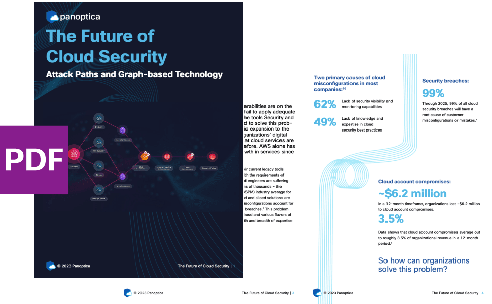
Unlocking Multi-Cloud Security: Panoptica's Graph-Based Approach
Discover why security teams rely on Panoptica's graph-based technology to navigate and prioritize risks across multi-cloud landscapes, enhancing accuracy and resilience in safeguarding diverse ecosystems.
Related articles


The Shift keeps you at the forefront of cloud native modern applications, application security, generative AI, quantum computing, and other groundbreaking innovations that are shaping the future of technology.